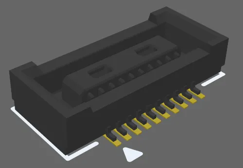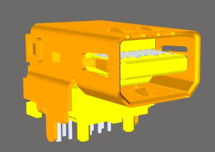
A PCB component footprint completed with a 3D Body.
A 3D body is a primitive design object that is used as a container into which a standard-format generic 3D model can be imported to represent the three-dimensional shape of the physical component that is mounted on the assembled PCB. The actual 3D shape is displayed when the editor is switched to 3D display mode (click View » 3D Layout Mode or press the 3 shortcut).
3D models are available from many component manufacturers and community websites. The following file formats are supported:
-
STEP – *.Stp and *.Step
-
SOLIDWORKS parts – *.SldPrt
For information on SOLIDWORKS versions from which exported *.SldPrt files are supported by import to Altium Designer, refer to the Mechanical Data Import-Export Support page.
-
Parasolid Models – *.x_t and *.x_b
Placing 3D Body objects to define the components' shape allows you to get a real sense of the arrangement of the components on the assembled board. As well as being able to see what the finished board will look like, real-time 3D clearance checking can be performed, allowing component-to-component and component-to-housing collisions to be detected during the design stage.
A 3D Body is normally placed in the PCB footprint editor as part of the PCB footprint. The footprint defines the connection points and the area-of-board that the component occupies and is the minimum required for board design. The 3D Body is optional; it can be added to the footprint to define the envelope of the component that mounts on that footprint.
3D model support is not limited to components. It also can be used to import other mechanical detail such as a bracket or the finished enclosure. Import the enclosure directly into the PCB editor.
While placing generic 3D models is a recommended way of using 3D Body objects as this provides an accurate and detailed component representation on the PCB and gives more accurate 3D collision testing in the PCB editor, a 3D Body object can also be used for placing extruded polygon, cylindrical and spherical 3D Body shapes either in the PCB editor or into a PCB library component footprint. For information about working with these objects, see the
Working with Extruded, Spherical & Cylindrical 3D Bodies in Altium Designer page.
3D Body Object Placement
A generic model, such as a STEP-format component model, is placed by linking or embedding it in a 3D Body object.
To place a generic model embedded inside the PCB footprint or PCB document:
-
Choose the Place » 3D Body command from the main menus or use the 3D Body command (
 ) on the Active Bar.
-
In the standard Windows Open dialog that appears after launching the 3D Body placement command, select the required file type from the drop-down then browse and locate the required model file, and click Open. The cursor will change to a crosshair, with the selected 3D model floating on it.
-
Press Tab to pause placement and display the Properties panel in 3D Body mode. The pause button overlay (
 ) will appear in the design space, indicating that you can access the fields of the Properties panel. The Generic 3D Model Type will be selected in the panel, along with Embed Model as the 3D Body source (means that the 3D model file is to be embedded inside the PCB library or PCB file).
-
The default model color can be overridden if required. In the Display section of the panel, enable the Override Color checkbox then set the Color and the Opacity as required.
-
Once editing in the panel is complete, click the pause button overlay to return to the design space.
-
The model will be floating on the cursor; position it then click to place.
-
The default behavior of the software is to remain in placement mode. Position further models if needed or right-click to exit model placement mode.
-
It is quite likely that the generic model will need to be re-oriented; refer to the Orienting and Positioning the 3D Model section of the Additional Tools for Working with 3D Bodies page to learn more.
To place a generic model that uses a source other than Embed Model (Server or Link to Model):
-
Select the Place » Extruded 3D Body command from the main menus or the
 icon on the Active Bar. The cursor will change to a crosshair and you will be in the default placement mode, placing an Extruded 3D Body object.
-
Press Tab to pause placement and display the Properties panel in 3D Body mode. The pause button overlay (
 ) will appear in the design space, indicating that you can access the fields of the Properties panel.
-
In the 3D Model Type region of the Properties panel, click the Generic button.
-
In the Source section of the Properties panel, click to set the source to:
-
Server – the 3D model is to be retrieved from a Workspace. Then click the Choose button to open the Choose Item dialog in which you can access content in a connected Workspace. Refer to the Referencing a Workspace-based 3D Model section below to learn more.
-
Link to Model – the 3D model file is linked to the PCB, this option is not available in the PCB library editor. Then click the Choose button to open the
![]() Choose Model dialog in which you can select the required model. If the required model location is not listed in the Choose Model dialog, refer to the Working with a Linked Model section below to learn more.
Choose Model dialog in which you can select the required model. If the required model location is not listed in the Choose Model dialog, refer to the Working with a Linked Model section below to learn more.
-
You will return to the Properties panel, with the chosen model information displayed.

Accurate and detailed component models are available.
-
A 3D model is imported into a 3D Body object. If you click to select an MCAD model in the PCB library editor, the Properties panel will show the properties of the 3D Body object containing that MCAD model.
-
Prior to the placement of a 3D Body, you can allocate a component layer pair of the
3D Body type that will contain 3D bodies. Refer to the Working with Mechanical Layers page to learn more about mechanical layers and component layer pairs.
-
Various options are available for checking clearance between components, including a mode that allows one 3D model to fit within another. Refer to the Component Clearance design rule to learn more.
-
3D mechanical models can sometimes be sourced from the component manufacturer.
-
There are excellent community portal websites, such as 3D Content Central and GrabCAD, where designers share models.
-
There is also a growing number of commercial 3D sites, including PCB 3D.
If you cannot see the 3D bodies in the PCB or PCB footprint editor, press
L to open the
View Configuration panel and ensure the
Show 3D Bodies option is set to
On in the
General Settings region on the
View Options tab (shortcut:
Shift+Z).
Working with a Linked Model
Typically this feature is used to link to a large MCAD model, such as the product case, that you want to place in the PCB editor to check the loaded board for fit. The advantage of linking the model is that if the software detects that an external linked model file has been updated, it will warn on file-open, allowing the linked model to be refreshed.
Linked models must be stored in a location that is defined on the PCB Editor – Models page of the Preferences dialog. If the required location is not listed in the Choose Model dialog, click the Add Directories button to open the Preferences dialog.
To add a new location in the PCB Editor – Models Preferences page:
-
Either type in the full path or click the button to the right of the Model Search Path field (
 ) to open the Windows Browse for Folder dialog.
-
After locating the required folder and clicking OK in the dialog, you will return to the Preferences dialog. Click the Add button to include this location in the list of available model search paths.
-
Note that only the specified folder is searched for model files; sub-folders are not searched.
-
Once the required location has been specified, click OK to close the Preferences dialog and return to the Choose Model dialog.
Referencing a Workspace-based 3D Model
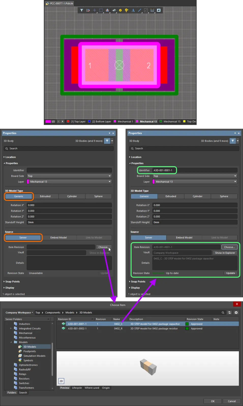
To reference a 3D model that is stored in a connected Workspace:
-
Select Server in the Source region of the 3D Body mode of the Properties panel.
-
Click the Choose button to the right of the Item Revision field.
-
The Choose Item dialog will open; use this dialog to browse to and select the revision of the required Workspace 3D Model.
-
After clicking OK, a link will be created between the 3D Body and the target revision of the Workspace 3D Model. Evidence of this link can be seen back in the Properties panel. Note that the Identifier field for the 3D body will be filled with the Item-Revision ID of the linked Workspace 3D Model.

Linking a 3D Body object to a revision of a Workspace 3D Model
Graphical Editing
The graphical method of editing allows you to select a placed 3D body object directly in the design space and change its location graphically.
Click on the 3D body then drag to reposition it. While dragging, the 3D body can be rotated or mirrored:
-
Press the Spacebar to rotate the 3D body counterclockwise or Shift+Spacebar for clockwise rotation. The Rotation Step size is defined on the PCB Editor – General page of the Preferences dialog.
-
Press the X or Y keys to mirror the 3D body along the X-axis or Y-axis.
Non-Graphical Editing
This method of editing uses the associated Properties panel mode to modify the properties of a 3D Body object.
3D Body Properties

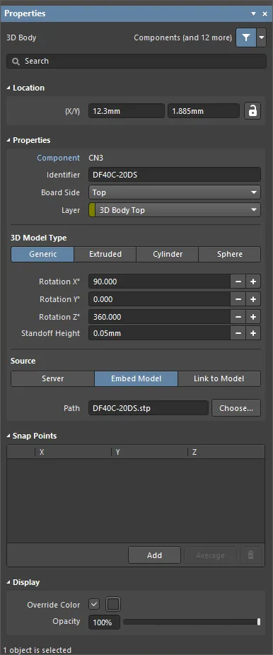
The 3D Body mode of the Properties panel.
Location
The

(locked) icon to the right of this region must be displayed as

(unlocked) in order to access the below fields. Toggle the lock/unlock icon to change its lock status.
-
(X/Y)
-
X (first field) - the current X (horizontal) coordinate of the reference point of the 3D Body, relative to the current design space origin. Edit to change the X position of the 3D Body. The value can be entered in either metric or imperial, include the units when entering a value whose units are not the current default.
-
Y (second field) - The current Y (vertical) coordinate of the reference point of the 3D Body, relative to the current origin. Edit to change the Y position of the 3D Body. The value can be entered in either metric or imperial, include the units when entering a value whose units are not the current default.
Properties
-
Component – this field is shown in the PCB editor only when the selected 3D Body is a constituent part of a PCB Component and displays the designator of the parent PCB component. Select the clickable Component link to open the Component mode of the Properties panel for the parent component.
-
Identifier - enter a human-readable name used to identify the 3D Body object. Identifiers are useful for selecting a 3D body in the PCB panel.
-
Board Side - use the drop-down to select from which side of the board the 3D Body will project. This setting is automatically changed if the 3D Body object is flipped to the other side of the board as part of a component flip.
-
Layer - use the drop-down to select on which layer the 3D Body exists. Only layers that are currently enabled are available. If the chosen layer is paired, then when the body is flipped to the other side of the board as part of its component, it will also be moved to the paired layer.
3D Model Type
Select a model type for the 3D body object from the available options: Generic, Extruded, Cylinder, or Sphere. The options vary for each type and provide controls necessary for sizing and positioning in the 3D design space.
-
Generic - when this option is chosen, the 3D Body object acts as a container for it and it is automatically resized to enclose the chosen model.
-
Rotation X° - the angular rotation (in degrees) of the 3D model around the X-axis. Click the +/- buttons to change the angular rotation in 9
0° increments or type in the value manually.
-
Rotation Y° - the angular rotation (in degrees) of the 3D model around the Y-axis. Click the +/- buttons to change the angular rotation in 9
0° increments or type in the value manually.
-
Rotation Z° - the angular rotation (in degrees) of the 3D model around the Z-axis. Click the +/- buttons to change the angular rotation in 9
0° increments or type in the value manually.
-
Standoff Height - the distance from the board surface to the underside of the 3D model. Click the +/- buttons to increase or decrease the value or type in the value manually. Use a negative value for a model that must pass down through the PCB.
-
Source
-
Server
-
Item Revision - the revision of the required 3D Model Item. Click the Choose button to the right of the Item Revision field to open the Choose Item dialog. Use this dialog to browse to and select the desired revision. After clicking OK, a link will be created between the 3D Body and the target revision of the 3D Model item.
-
Vault - displays the target server. Use the Show in Explorer button to open the Explorer panel.
-
Details - displays the revision details.
-
Revision State - displays the status of the linked 3D Model item.
-
Update - if a newer revision of the linked Item is available, click to use the latest revision.
-
Embed Model - use to select a 3D model (STEP, Parasolid, SolidWorks Part) to embed.
-
Path - click Choose to search for and select the path of the model.
-
Link to Model - use to link to a 3D Model.
-
Path - click Choose to search for and select the path of the model. Click
 to refresh the path.
-
Extruded
-
Overall Height - the distance from the board surface to the top side of the extruded body.
-
Standoff Height - the distance from the board surface to the underside of the extruded body. Click the +/- buttons to increase or decrease the value or type in the value manually. Use a negative value for extruded bodies that must pass down through the PCB.
-
Texture
-
Texture File - defines an image to be displayed on the top surface of the extruded body. Accepted file formats are
*.bmp, *.dds, *.dib, *.hdr, *.jpg, *.pfm, *.png, *.ppm, and *.tga. Click  to open a dialog to search for and select the desired file.
-
Center - the X and Y offsets that the center of the texture image will have with respect to the center of the top surface of the extruded body. For example, a value of 100mil, 0mil will shift the center point of the image 100mils in the X direction from the center point of the top surface of the extruded body.
-
Size - the width (X-direction) and height (Y-direction) of the texture image. By default, the texture image will be uniformly scaled to fit the bounds of the top surface of the extruded body.
-
Rotation - the rotation of the extruded body.
-
Cylinder
-
Height - the height of the cylindrical body.
-
Radius - the radius of the cylindrical body.
-
Rotation X° - the angular rotation (in degrees) of the cylindrical body around the X-axis. Click the +/- buttons to change the angular rotation in 9
0° increments or type in the value manually.
-
Rotation Y° - the angular rotation (in degrees) of the cylindrical body around the Y-axis. Click the +/- buttons to change the angular rotation in 9
0° increments or type in the value manually.
-
Rotation Z° - the angular rotation (in degrees) of the cylindrical body around the Z-axis. Click the +/- buttons to change the angular rotation in 9
0° increments or type in the value manually.
-
Standoff Height - the distance from the board surface to the underside of the cylindrical body. Click the +/- buttons to increase or decrease the value or type in the value manually. Use a negative value for a cylindrical body that must pass down through the PCB.
-
Sphere
-
Radius - the radius of the spherical body.
-
Standoff Height - the distance from the board surface to the lowest edge of the spherical body. Click the +/- buttons to increase or decrease the value or type in the value manually. Use a negative value for a spherical body that must pass down through the PCB.
Snap Points
-
Grid region - displays the X, Y, and Z snap points for the sphere.
-
Add - click to add a new snap point.
-
Average - click to use the averages of all selected snap points for one individual snap point. This option is available only when two or more snap points are selected in the grid.
-
 - click to delete the selected snap point.
Display
-
Override Color - enable if desired, then click the color box to access options to specify the object's color.
-
Opacity - use the slider bar or enter the percentage directly to specify the transparency of the 3D body from invisible (left-most) to completely opaque (right-most).
This setting is a permanent setting for this object, however, it is also possible to adjust the object opacity temporarily in the PCB panel when it is set to 3D Models mode.